ROHDE & SCHWARZ UHF FIELD-STRENGTH INDIKATOR 470-850MHz HUZE


ROHDE & SCHWARZ UHF FIELD-STRENGTH INDIKATOR 470-850MHz TYPE HUZE
Instruction Book
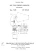
UHF FIELD-STRENGTH INDIKATOR
470-850MHz
TYPE HUZE BN 15015/2
Edition R 11608/1266
(Translation of German edition R 10809/466)
(service manual)
English language
55 pages
Text/images/schematics 300dpi 20 levels grayscale lossless LZW, lossless ZIP PDF compression, 18 MBytes
Table of Contents
1. Specifications
1.1 UHF Receiver BN 150151/2
1.2 UHF Antenna BN 150152/60
1.3 Use as Field-strength Indicator
1.4 Accessories Supplied
1.5 Recommended Accessories
2. Uses
Operating Instructions
3.1 Setting the Mechanical Zero of the Meter
3.2 Calibrating the Set
3.3 Field-strength Measurement
3.3.1 Connecting the Antenna
3.3.2 Measurement
3.3.3 Measurement Using a Different Antenna
3.4 Voltage Measurement
3.4.1 Applying the Voltage to be Measured
3.4.2 Measurement
3.5 Modulation Monitoring
3.6 Recording
3.7 IF Output
4. Description
4.1 General
4.2 Antenna
4.3 RF Section
4.4 IF and AF Sections
4.5 Power Supply
4.6 Charger for UHF Field-Strength Indicator Type HUZE
4.7 Notes on the Correction Curves
4.7.1 Voltage Correction Factor k
4.7.2 Field-strength Correction Factor kt
5. Maintenance
5.1 Charging the Storage Batteries
5.2 Replacing the Storage Batteries
5.3 Calibrating the Instrument
5.4 Repairs
6. Parts List
6.1 Attenuttor
6.2 RF Section
6.3 IF and AF Sections
6.4 Front-panel Wiring
6.5 Charger BN 150156
Fig. 1 Nomogram for converting dB values into voltage or field-strength units
Fig. 2 Front View with antenna connected for field-strength measurement and with charger BN 150156 connected
Fig. 3 Simplified Diagram
Fig. 4 Chassis, Top VieW
Fig. 5 Components Location Plan for IF and AF sections
Fig. 6 Circuit Diagram of UHF Field-Strength Indicator Type HUZE incl. Charger BN 150156
Fig. 7 Radiation Pattern of the Antenna BN 150152/60 at 400 MHz
Fig. 8 Radiation Pattern of the Antenna BN 150152/60 at 500 MHz
Fig. 9 Radiation Pattern of the Antenna BN 150152/60 at 650 MHz
Fig. 10 Radiation Pattern of the Antenna BN 150152/60 at 800 MHz
Fig. 11 Radiation Pattern of the Antenna BN 150152/60 at 850 MHz
Fig. 12 Antenna factor 2/heff of the Antenna BN 150152/60 for determining the rield strength from the voltage at receiver input
Keywords: huze;field-strength;schwarz;rohde
File Size: 17.5 MBytes
| Embed: |
|
 huze;field-strength;schwarz;rohde
284898406
29.00
thetechman
Fresh Download
Available!
huze;field-strength;schwarz;rohde
284898406
29.00
thetechman
Fresh Download
Available!